The Compound Fertilizer Production Line plays a pivotal role in modern agriculture by ensuring that fertilizers are produced with consistent quality and granule size. Uniform ferti...
READ MOREWire Belt Hoist
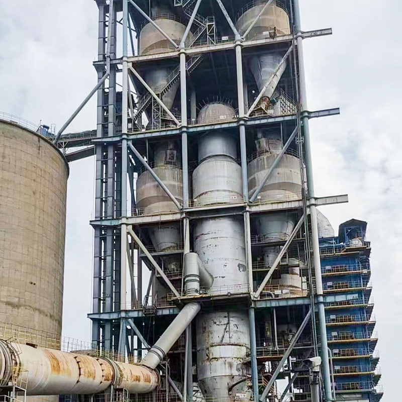
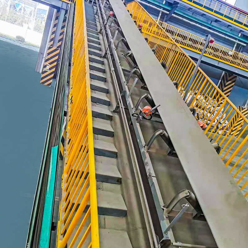
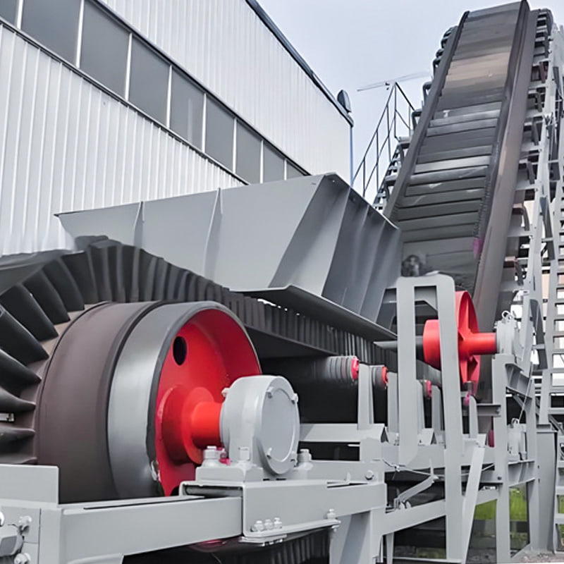
The wire belt hoist features high conveying capacity, compact size, low power consumption, stable and reliable operation, long service life, and the ability to achieve ultra-high lifting heights on a single unit. This next-generation product, developed by our company by integrating new international technologies with domestic production and application experience, is suitable for vertical conveying of dry bulk powders or granular materials. It is widely used in high-load conveying systems for powders and granular materials in industries such as cement, chemicals, coal, power, ports, and grain. It is particularly recommended for conveying raw meal into the kiln of new dry-process cement plants, conveying material into large raw meal homogenization silos and cement silos, and high-load circulating material conveying in closed-circuit systems of large ball mills, completely replacing imported equipment of the same specifications. Currently developed products have a maximum conveying capacity exceeding 1800 m³/h and a maximum conveying height of 180 m.
-
SPECIFICATIONS
-
CONTACT US
-
Performance Features
1. Lifting height up to 180m;
2. Conveying capacity exceeding 1800m³/h;
3. Material temperature up to 130°C;
4. Closely spaced hoppers ensure continuous material extraction and discharge;
5. Equipped with anti-slip (slip switch) and material blockage detection (level meter);
6. Automatic centering design for head and tail drums;
7. Split drum rubber coating available for easy replacement;
8. Automatic tail balancing device for automatic tensioning;
9. Hard aluminum alloy belt connector for reliability, stability, and lightweight;Structural Components
This series of elevators consists of a drive unit, head unit, platform and guardrail, intermediate housing, maintenance housing, connecting channel steel frame, connecting plate, hopper, belt, connector, tail unit, level meter, and slip mechanism. See the schematic diagram.1. Drive Unit
This section consists of the motor, hydraulic coupling (elastic coupling), reducer, auxiliary drive, chassis, and hinged support. The hydraulic coupling (elastic coupling is used when the motor power is less than 30 kW) provides a certain starting cushioning protection for the motor and reducer. The auxiliary drive is used during maintenance and commissioning.
2. Head
The head consists of the upper cover, head housing, spindle assembly, dust collection port, platform, maintenance stand, and guardrail. The platform, maintenance stand, and guardrail are bolted or welded on-site. The spindle assembly bearing seat requires fine-tuning during commissioning to achieve the required position. After adjustment, tighten the adjustment bolts.
3. Standard and Non-standard Sections
The standard and non-standard sections are the intermediate housings shown in the figure. They provide support and protection.
4. Maintenance Section
The maintenance section features a large access door for loading the traction unit and hopper, and provides convenient access for routine maintenance and inspection. This section is located near the tail section, above the tail section. The engineering design requires the installation of an inspection platform (completed by the civil engineering department) at the same height as the lower flange of this section. Equipment heights exceeding 40m require two maintenance sections to balance the pressure differential between the two channels.
5. Channel Steel Frame and Connecting Plate
The channel steel frame and connecting plate stabilize the dual-channel intermediate casing and enhance the vertical rigidity of the machine.
6. Tail Section
The entire weight of the elevator includes the driven roller, casing, counterweight box, level meter, runout sensor, feed inlet, feed inlet flange, hanger, and other components.
7. Level Meter
The level meter is installed at the tail section. The mounting holes are pre-cut at shipment and are installed and debugged on-site before commissioning. When the material level at the tail section reaches the specified level (the level meter's mounting position on the casing), the level meter generates a signal, causing the upstream equipment of the elevator to reduce or stop feeding (this can be set in the DCS system). Alternatively, the signal can be used to check for feed deviation and severe wear on the discharge plate, which could result in leakage or backflow.
8. Runout Sensor
The runout sensor is installed on the left and right ends of the head and tail sections. When the belt deviates beyond a specified position, the deviation sensor issues a signal. In this case, the elevator's upstream feeder should be shut down. Wait until the elevator hopper is empty before stopping the machine. The cause of the deviation should be checked and any adjustments made.
9. Traction Unit and Hopper
The traction unit and hopper consist of the hopper, bolts, gaskets, tape, and joints. Driven by the drive roller, the belt, hopper, tail pulley, and counterweight generate tension, causing the belt and hopper to move, achieving vertical material transport. The tail pulley shaft is not fixed to the tail housing. When the traction unit is stretched, the preload force allows the tail pulley shaft to move freely up and down, maintaining a constant tension. -
Message Feedback
-
-
A Compound Fertilizer Production Line is a complex system designed to transform raw materials into high-quality compound fertilizers efficiently and consistently. These production ...
READ MORE -
A Compound Fertilizer Production Line is a highly integrated industrial system designed to manufacture compound fertilizers efficiently. Unlike single-nutrient fertilizers, compoun...
READ MORE -
The demand for agricultural products continues to grow globally, driving the need for more efficient and higher-capacity Compound Fertilizer Production Line operations. Scaling up ...
READ MORE

 En
En
 English
  Français
  русский
  中文简体
中文简体  عربى
عربى  Español
